By reading this text you are granted the rights outlined below. This user-agreement is an attempt at formulating an 'offline art licence' stipulating the following:
This archive contains the files and instructions to create your own rolling 'offline'1 wifi gallery space utilising shared scooters outfitted with induction wireless charging pads.
The files presented here have been collected for the OPENCOIL speedshow that explores the impact of these 'micro-mobility services' on urban space by sharing the same decentralised infrastructure2 for an exhibition space that attempts to address the conditions, effects and affects of these infrastructures.
The artistic contributions are each stored on a Wifi enabled microcontroller attached to a scooter in a non invasive nor destructive manner. To view the works, one connects to the local unencrypted WiFi network advertised by the Wifi microcontroller. When connecting using Apple3 devices, a web portal opens automatically, showing the work, no mobile data connection necessary. All works have been specially optimised by the artists to be viewed on smartphones.
OPENCOIL is in no way associated with these micro-mobility services, but merely shares the existing scooter network. The conversion of the scooters into an exhibition space is completely reversible and in no way restricts the conventional use of the scooters (even during the exhibition). The scooters will not be damaged.
The exhibition will start on October 26th in the public space in front of Zentrum für Netzkunst (Haus der Statistik). For one week, until November 1st, the exhibition will be serviced and kept running daily by our team. Should a work be damaged or not be found, please send an e-mail (service@opencoil.show) or use the Telegram App (https://t.me/opencoil)
After this date this how-to will continue to roam the streets and will never be made available online. Now do it yourself!
1. As in 'offline art' by Aram Bartholl based on the PirateBox initiative.
2. A certain branch of micro-mobility services deploy 'dock-less' sharing vehicles, meaning they don't need to be rented from nor returned to a designated parking spot. This raises questions on convenience, maintenance and use of public space. This 'decentralisation' is reflected in the company itself, where various responsibilities are outsourced; renting is done via a centralised API, repairs are done in a centralised warehouse, units are recharged by a fleet of roaming 'juicers' (lime) or 'hunters' (voi) or 'rangers' (tier) as gig work/minijob), carbon offset and recycling responsibilities are outsourced to external companies (for example: climatepartner.com and deutsche-recycling.de).
3. Android devices might present a message offering you to 'sign in' or a warning the network does not have an internet connection. Click the pop-up message and select the option 'use (network) as-is' to use the network without and internet connection and visit any random URL in a browser to view the artworks (http://ya.ru is a good one). If all goes well, you will be redirected to the artwork.
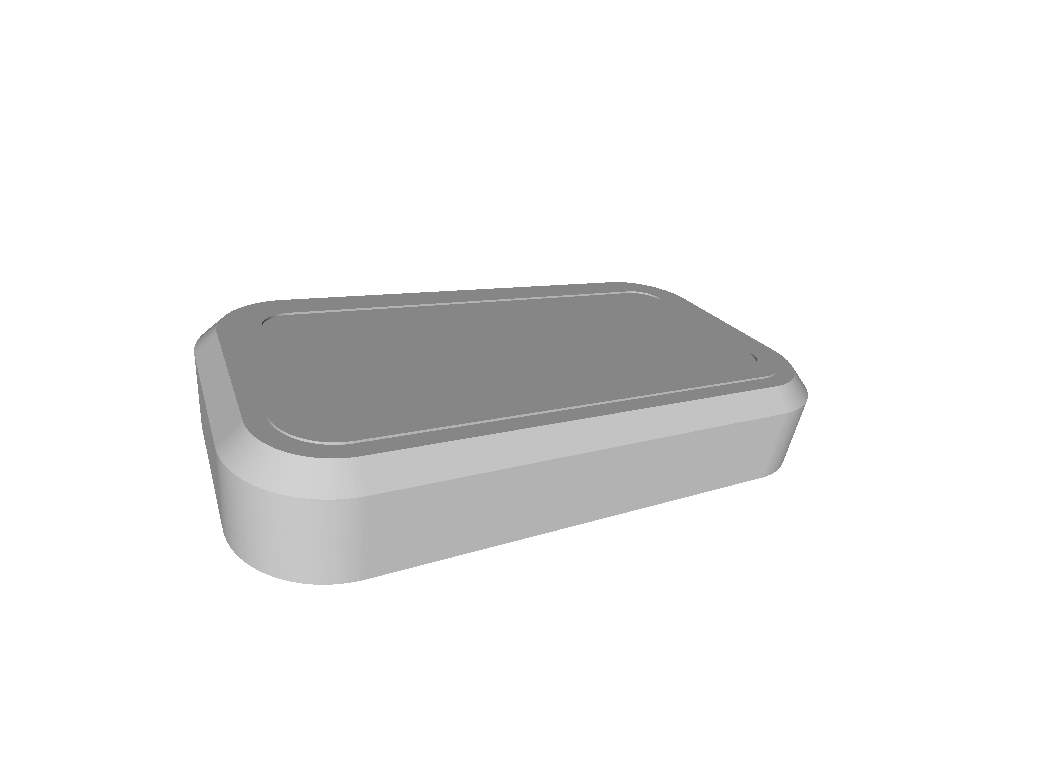
In this Archive you will find a 3d printable .stl file that will allow you to print a mould for vacuum forming the charging pad cover.
To make the vacuum formed charging pad cover look more symbiotic, one could use the included template to lasercut a spray paint stencil.
To even-out the electronics underneath the vacuum formed mould you can use 2 to 3 mm cardboard stock as as spacer. A lasercutting template to cut the cardboard stock is provided here
 From left to right: logo stencil, vacuum formed mould with cardboard inlay, vacuum formed mould with logo, cardboard inlay
Here you will find an Arduino sketch for the ESP8266 wifi enabled microcontroller that provides a non-encrypted wireless access point called 'example code' running a webserver that serves files stored on its 'SPIFFS' filesystem (stored at here).
This guide assumes you have a 4MB ESP12F microcontroller and use Arduino IDE.
For ESP12F use the following settings in Arduino IDE
These settings give you about 2.471 KB of SPIFFS storage space for files and ~512KB sketch size
The website served on the ESP12F lives in the 'data' folder inside the Arduino sketch folder. To upload this data you need the 'Arduino ESP8266 filesystem uploader' plugin. Find it here: https://github.com/esp8266/arduino-esp8266fs-plugin.
To upload files to the ESP12F using the Arduino IDE click: Arduino > Tools > ESP8266 Sketch Data Upload (make sure you installed it in the correct directory path). Close the Serial Monitor prior to uploading data.
You can upload your sketch and files wirelessly, there is one caveat: SPIFFS file uploads don't work with password protected uploads (line 42). Workaround: flash your sketch with line 42 commented out. Upload your files to SPIFFS, then uncomment the line and upload the code.
 Fully assembled electronics, left to right, top to bottom: ESP12F (unshielded), AM1117 regulator, coil.
NOTE: Be aware that these 'adaptor coils' could contain additional circuitry that condition the output for use with specific mobile phones (the pearl.de ones do). Below is a guide to modify the 'pearl' coils to deliver maximum voltage (5v)constantly, instead of switching to low power, 2.5v output when not enough/too much current is drawn.
If you have soldered all components together and your ESP12f won't boot, you might have to modify your charging coil+circuit a bit. To make sure it's the coil, measure the output of the coil's electronics on the + and - (GND) terminals. If your multimeter reads ~2.5 volts you need to modify the circuit. (Disclaimer: the exact details on how this circuit works are yet unclear, comparing to a working coil revealed several differences in the electronics, matching them up made the non working coil output the needed 5v).
You need to desolder two IC's/ chips following the (visual) guide below. The electronics and coil are sandwiched between two layers of foil. To peel the foil away look for an opening near the lightning connector.
You are then left over with the bare coil and flexible pcb. Here I already desoldered the lightning connector flex pcb.
Remove the following chips indicated by the following silkscreen printing: * Q3 (chip markings: p7) * Q4 (chip markings: wsc7)
A hot air reworking station + tweezers will make quick work of that (settings: 1 second on 320deg, moderate airflow). Without hot-air you could try a soldering iron or fine wire-cutters to simply cut away the chips. The flexible PCB is very fragile though.
Step 1 completed!
With both chips removed, you have to bridge two of the three (now) bare connections of the transistor Q4. I could not find a datasheet on this transistor so please refer to the photo's to see which pins.
Done!