| .. | ||
| coil-mod | ||
| esp-wireless-charging-pcb | ||
| esp-wireless-charging-v2 | ||
| outline-pcb-temp.svg | ||
| README.md | ||
opencoil-paracity: electronics
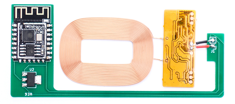
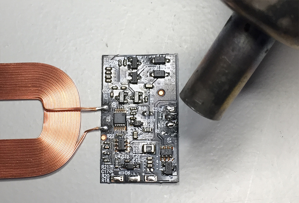
Assembled pcb v1
As of 2022 there is a PCB version 2 with extra breakout gpio pins, schematic here
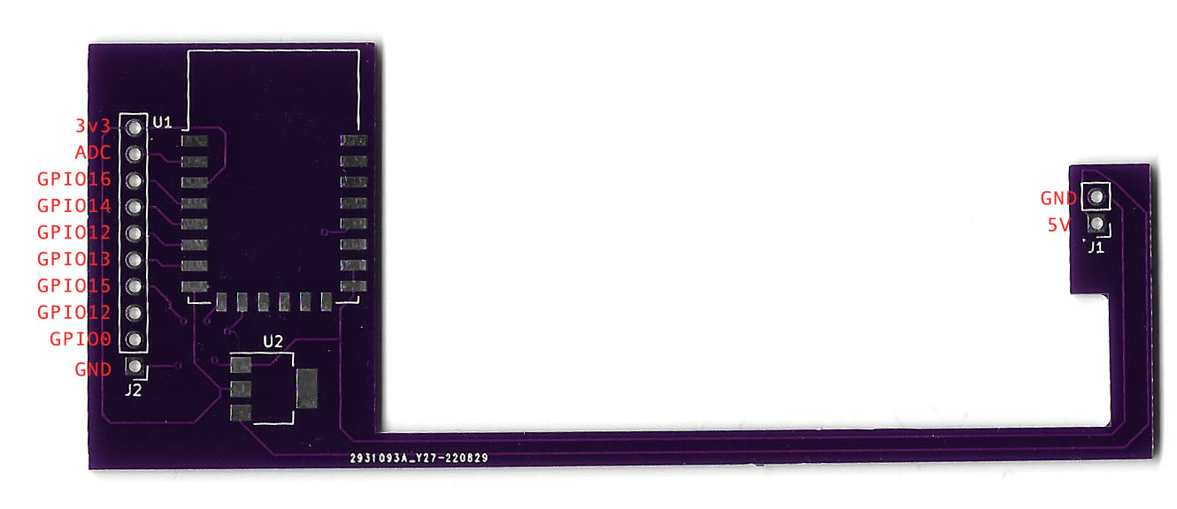
Assembled pcb v2
Bill of Materials
- PCB: Send the gerbers from this repo to your fab of choice.
- ESP12F: Widely available.
- AM1117 3.3v Regulator: Widely available.
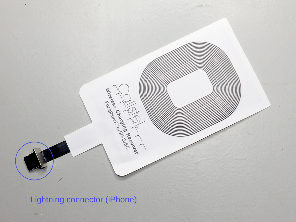
- QI compatible wireless charging coil delivering 5v and > 500 mA: For example this, search keywords: "pcba receiver module qi". Alternatively you could repurpose 'adaptor coils' advertised to convert non-QI phones to wireless charging, such as these*.
NOTE: Be aware that these 'adaptor coils' could contain additional circuitry that condition the output for use with specific mobile phones (the pearl.de ones do). Below is a guide to modify the 'pearl' coils to deliver maximum voltage (5v)constantly, instead of switching to low power, 2.5v output when not enough/too much current is drawn.
Modding 'adaptor coils'
If you have soldered all components together and your ESP12f won't boot, you might have to modify your charging coil+circuit a bit. To make sure it's the coil, measure the output of the coil's electronics on the + and - (GND) terminals. If your multimeter reads ~2.5 volts you need to modify the circuit. (Disclaimer: the exact details on how this circuit works are yet unclear, comparing to a working coil revealed several differences in the electronics, matching them up made the non working coil output the needed 5v).
Step 1
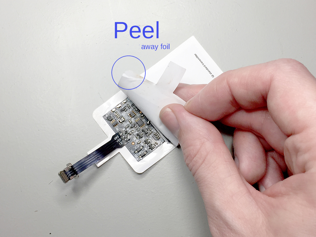
You need to desolder two IC's/ chips following the (visual) guide below. The electronics and coil are sandwiched between two layers of foil. To peel the foil away look for an opening near the lightning connector.
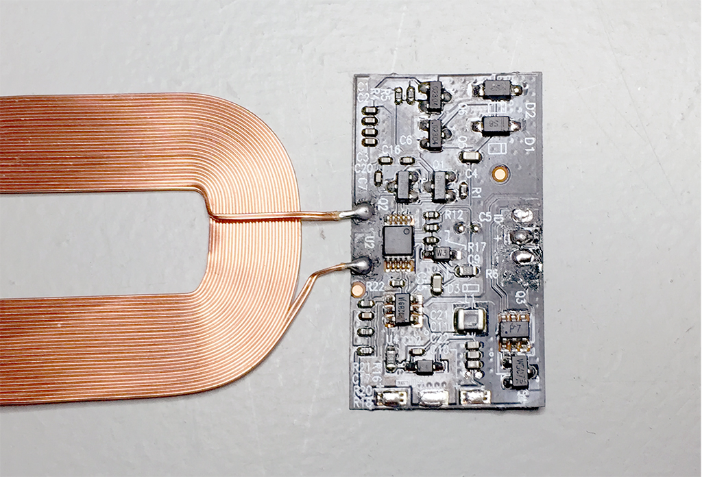
You are then left over with the bare coil and flexible pcb. Here I already desoldered the lightning connector flex pcb.
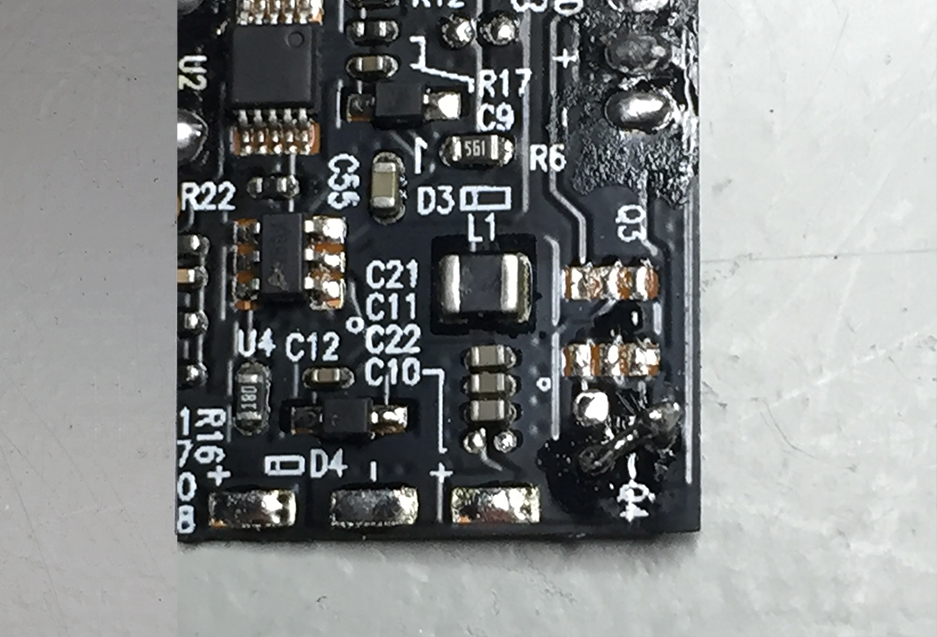
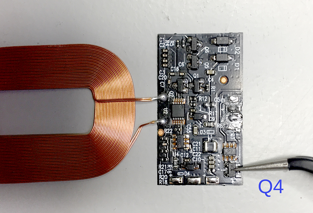
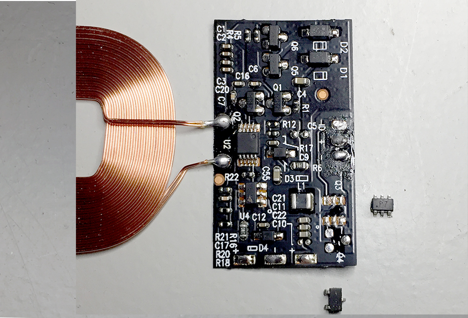
Remove the following chips indicated by the following silkscreen printing:
- Q3 (chip markings: p7)
- Q4 (chip markings: wsc7)
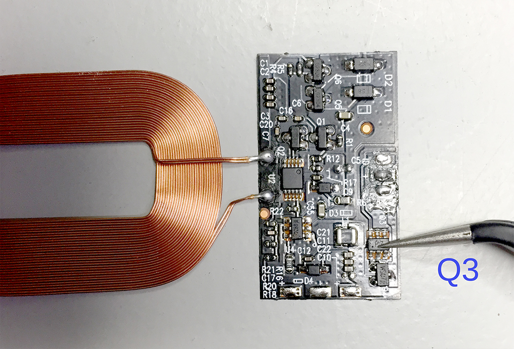
A hot air reworking station + tweezers will make quick work of that (settings: 1 second on 320deg, moderate airflow). Without hot-air you could try a soldering iron or fine wire-cutters to simply cut away the chips. The flexible PCB is very fragile though.
Step 1 completed!
Step 2
With both chips removed, you have to bridge two of the three (now) bare connections of the transistor Q4. I could not find a datasheet on this transistor so please refer to the photo's to see which pins.
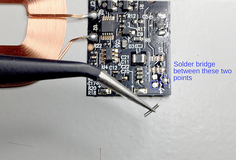
Done!