2.2 KiB
opencoil-paracity: electronics
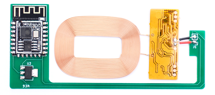
Assembled pcb
Bill of Materials
-
PCB: Send the gerbers from this repo to your fab of choice.
-
ESP12F: Widely available.
-
AM1117 3.3v Regulator: Widely available.
-
QI compatible wireless charging coil delivering 5v and > 500 mA: For example this, search keywords: "pcba receiver module qi". Alternatively you could repurpose coils advertised to convert non-QI phones to wireless charging, such as these*.
-
NOTE: Be aware that these 'converter pads' could contain additional circuitry that condition the output for use with specific mobile phones (the pearl.de ones do). Below is a guide to modify the 'pearl' coils to deliver maximum voltage (5v)constantly, instead of switching to low power, 2.5v output when not enough/too much current is drawn.
Modding Coils/pads
If you have soldered all components together and your ESP12f won't boot, you might have to modifiy your charging coil+circuit a bit. To make sure it's the coild, measure the output of the coils electronics on the + and - (gnd) terminals. If your multimeter reads ~2.5 volts you need to modify the circuit. (Disclaimer: the exact details on how this circuit works are yet unclear, comparing to a working coil revealed several differences in the electronics, matching them up made the non working coil output the needed 5v).
Step 1
Take off the follwing chips indicated by the following silkscreen codes:
- Q3 (chip markings: p7)
- Q4 (chip markings: wsc7)
A hot air reworking station + tweezers will take quick care that (settings: 1 second on 320deg, modertate airflow). Withouth hotair you could try a soldering iron or fine wirecutters to simply cut away the chips. The flexible PCB is very fragile tho.
Step 2
With both chips removed, you have to bridge two of the three (now) bare connections of the transitor Q4. I could not find a datasheet on this transitor so please refer to the photo's to see which pins.