# tvaria
Experiments in audio-visual transmissions (tags: narrowcasting, microfm, microtv, radio, PAL, sstv)
[small demo video](http://dennisdebel.nl/workshops/read-and-repair/rr-transmitter.mp4)
[uncut live video tutorial](https://youtu.be/veM15vyBw1g)
## Prior Art
Based on Tetsuo Kogawa's simplest tv transmitter
https://anarchy.translocal.jp/microtv/howtotvtx.html
PDF: https://anarchy.translocal.jp/microtv/simplestTVtx03.pdf
Annotated PDF: https://git.vvvvvvaria.org/then/tvaria/src/branch/master/notes-on-kogawa-simplest-tv-tx.gif
## Disclamer
This is probably illegal in your counrty. Don't build this. What can you transmit with license:
* You have a HAM radio license and call sign (legally usable section of the band (6meter, 50MHz)) > TV signal's bandwidth is too high to be legally transmitted (4.5MHz). Only sstv is allowed on carrier: 50.510 MHz, with Bandwidth of: 1.2000Mhz (Our signal is 4.5Mhz....)
* 4 ingredients: Frequency, Bandwidth, Transmit Power, Mode
* Novice callsign:
* "Beperkte machtiging alleen voor de 40-m-, 20-m-, 10-m-, 2-m- en 70-cm-band met een maximum zendvermogen van 25 Watt. (https://www.ham-radio.nl/wp-content/uploads/2017/02/BANDPLAN-AMATEUR.pdf)"
* 144.500 - 144.800 MHz > all modes, 25 Watt, ...but yes..800KHz bandwidth, our signal is 4.5MHz (2 meter band)
* 434.000 - 435.000 MHz > experiments, atv, 25 Watt, 1Mhz bandwidth...image: AM modulated, soundFM modulated (https://www.pd3rfr.nl/modes/atv-amateur-televisie) (70 cm band)
(ref: https://www.by-rutgers.nl/Amateur%20frequentie%20banden.htm)
Instead of saying 144.500 MHz, these amateur bands are often refered to in meters rather than frequencies. These are the literal wavelenghts of the signal. The 'meter' bands are calculated by speed of light in a vacuum 300 million meters per second divided by frequency in million Hertz/sec (so 300/50Mhz=6 = 'the 6 meter band' )
## Diagram of the setup
[TV] ....(air)..... [TRANSMITTER]---(RCA CABLE)---[RPI]---(INTERNET*)
*optional
## Making
### Tools Needed
* Side Cutters
* 5mm drill
* Soldering Iron
* Solder
* Small set of screwdrivers for tuning (plastic prefered)
* Utility knife
* Super Glue
Handy to have:
* Vernier Calipers
* Tweezers (to place components and not burn your fingers)
* Electrical tape to isolate the variable resistor from the ground plane
### Parts Needed
* Transitor - Kogawas japanese transitors are from the 1970's and unobtainable, but you can use practically any general purpose NPN transistor: BC547b, BC548b, 2N3904 just take notice of the pins and orientation.
link: https://octopart.com/bc547b-on+semiconductor-354110?r=sp
* 2x Variable Capacitors - Instead of 10PF, we used the 50PF Murata TZ03Z500F169B00 Trimmer Cap
link: https://octopart.com/tz03z500f169b00-murata-221555
* 2x Ceramic capacitor 0.01uF / 10nF / 103
link: https://octopart.com/mc0805y103m500a2.54mm-multicomp-9374526?r=sp
* 1x Electrolytic capacitor 100uF
link: https://octopart.com/eca2ahg101-panasonic-3656268?r=sp
* 1x 1k / 1000R / 102 Trimmer Potentiometer
link: https://octopart.com/pt6kh102a2020-piher-13709261?r=sp
* 1x 10K Ohm THT resistor: https://octopart.com/lr1f10k-te+connectivity-16077782?r=sp
* 1x 27K Ohm THT resistor: https://octopart.com/lr1f27k-te+connectivity-16077846?r=sp
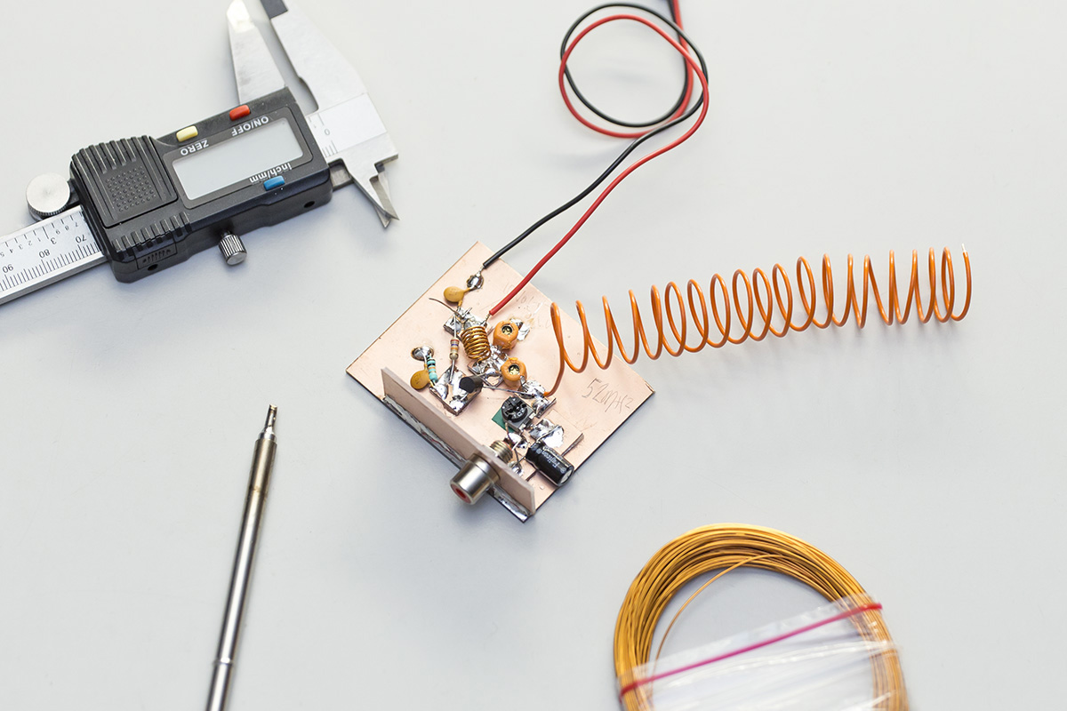
* DIY: 1x Coil: 7 turns, 0.7mm magnet wire/transformer wire (width 6.8mm), see below.
* 9 Volt Battery
* 9 Volt Battery Clip: https://octopart.com/233-keystone-20415?r=sp
* 60x40mm copper clad fr4: http://www.fortex.co.uk/product/fr4-uncoated-single-sided-copper-clad-pcb-laminate/
Complete Bill of Material:
https://octopart.com/bom-tool/QOJ00mDh
10 parts, total costs: $1.49 excluding the battery and tools needed.
### Winding coils
Use a 5mm drill bit to wind your coil around. (coil = 7 tight turns of 0.7mm (measured 0.6mm) around a 5mm drill bit, after winding TIGHT, spread the coil out to be around 6.7mm/7mm in lenght, coild-end to coil end...).
## Transmitting
### Possible hardware
* Anything putting out a 4MHz PAL (or NTSC?) signal: game consoles (NES), VCRS, Video Title Generators..or:
* Raspberry Pi 1 B (fcc id: 2ABCB-RPI21), the first raspbberry pi board (2011-2012) has fullsize composite out (RCA) plug, with correct polarity...
* Raspberry Pi 3b v2. It has composite out through the minijack trrs connector. NOTE: the ground and + are inverted on this plug... (so centerpin on yellow plug is ground and sleeve is your signal). This also affects the sound output on the trrs...great job rpi!
## Tuning the transmitter
Roughly 6 variables:
* Input Voltage
* Antenna (Type+ Size)
* Coil (Material, diameter, length, wire gauge)
* Variable Capatitor 1 and 2
* Variable Resistor
* You position to the transmitter(+ transmitter is microphonic like a contact mic)
Preferably you use plastic screwdrivers to adjust the variable caps and resistors..this is not always possible, maybe coating your screwdriver in non conductive paint could work.
The exact transmitting frequency will always be a surprise. Usingt a SDR like HackRF + software like GQRX helps to find your transmitter's frequency in its 'waterfall' display...You can also just 'auto-tune' your tv and wait until you see something, it prolly won't lock-on, so besure to stay ready to stop the auto scanning and do some manual tuning (also see: Building the transmitter below for more details).
## Software
In case you are using a Raspberry Pi to generate the analog video signal for your transmitter:
* this pi image: TODO
* enable PAL on rpi 1 (sdtv mode 2) in /boot/config.txt
* `$ sudo apt-get install omxplayer`, a command line media player that is designed for HW acceleration on the RPI. Its capable of playing video RTMP streams as well.
* connect to tty1 from ssh:
`$ sudo chmod 666 /dev/tty1`
`$ script tty1`
Playing / streaming youtube videos
NOTE: download / update to the LATEST youtube-dl!!
$ omxplayer `youtube-dl -g -f mp4 'YI4hzzepEcI'`
( can also be youtube ID, mind that when your ID has a dash, you must encapsulatethe id with single quotes)
(-f mp4: force mp4 (omxplayer cant play webm))
see: https://raspberrypi.stackexchange.com/questions/43245/omxplayer-doesnt-play-audio-when-streaming
## Receiving
Analog capable TV with antenna. We used an Amstrad CTV 140 with antenna input.
### Tuning your tv
It's handy to fisrt check your RPI composite output on the AV/AUX channel of your TV using a cinch/rca/tulip cable. It should be crisp and colorful. If so, you can go wireless. Else try to enable PAL on rpi 1 (sdtv mode 2?) in /boot/config.txt
When all is good, you can manually tune your TV to the beginning of the VHF1 band or just use 'auto tune' to find the transmitted signal.
Notes: this transmitter is designed and tested to work on the VHF1, also called 'Band 1' (47 to 68 MHz for the European Broadcasting Area), specifically on 50 MHz, allocated to amateur radio operators ('hams'). The bandwidth of the PAL signal is around 4.5MHz though, and might not be allowed on this frequeny...Also, this transmitter is rather dirty and can possibly transmit on other frequencies (multiples of the base carrier wave). A filter would be good...Trivia: The '6 Meter band' is called the 'magic band' because it shares the treasured porperties of both High Frequency (HF) and Very High Frequency (VHF) radio wave propagation, namely: skywave, meteorscatter and Multiple-hop sporadic E propagation allowing for intercontinental communications at distances of up to 10,000 kilometres.
### Receiving using Software Defined radio
Cheap rtl-sdr sticks dont have enough (4MHz) bandwidth to receive full color pal. Black and white is supposed to be possible using 'TV Sharp': https://www.rtl-sdr.com/analogue-tv-with-rtl-sdr/ (no sound, atleast not withouth 2 stikcs)!
## Improvements
Find a way to transmit legally on this band: Either look into SSTV (and use computers to receive using a cheap sdr dongle) or look into amateur televisie (ATV) that uses much higher frequencies (thus allowing for more bandwidth...but good luck hand soldering such a transmitter/receiver): https://vhf-uhf.veron.nl/atv/hoe-start-ik-met-amateur-televisie-atv/
* 3cm (10GHz)
* 6cm (5,7GHz)
* 13cm (2,3 GHz)
* 23cm (1,2 GHz)
* 70cm (434.25 MHz) < might be possible to hand solder...
(ref https://www.pe1rqm.nl/wat-is-amateur-televisie-atv/ )
* Filter (see above).
* Amplifier: increase the range of your dirty transmitter...not sure 'ham' radio amplifiers will workbecuase they are mainly focussed on CW, voice or other low-bandwith (far reaching) signals.PALis4.5MHZ wide..and proly not allwed on the band <<< dikke 'space bug' as described here: line 6: https://pad.vvvvvvaria.org/bugs (possible amp: http://users.belgacom.net/hamradio/schemas/vhfamp1.gif)
* Sound: there is no sound. Again Kogawa might have an answer: https://anarchy.translocal.jp/microtv/how_to_advancedTVTX_p0.html
## Link Dump
https://www.youtube.com/watch?v=rmGAd_MVaWw (hacking variable inductor to add audio to your fm tv transmitter)
https://www.youtube.com/watch?v=3sVIOg-PlKc (video tutorial of kogawa fm audio transmitter)